Showing posts with label dcc. Show all posts

Tuesday, 17 September 2013

Review of the Hornby R3120X LNER J83 00 Gauge DCC Fitted Steam Locomotive

The R3120X is a Railroad model. It bears stating up front, just so you realise that the price tag will probably reflect the build quality. Usually, Railroad also means D-ring couplings moulded onto a Lima style chassis.

In this case, I was mislead slightly by the Amazon description, which indicates that it has NEM pockets. If this is the case, then they've hidden them well.

I'd err on the side of caution and say that, from the picture below, these are moulded Lima style D-ring couplers, rather than NEM couplings as listed. (If anyone knows differently, please let me know in the comments section!)
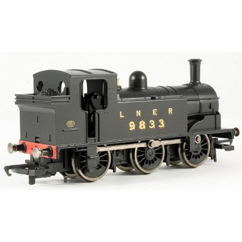
(Thanks to Papamallard for the picture)

Still, it is a handsome J83, at a reasonable price.If you can get it for the 40 - 50 GBP range, including delivery, that is. So, what makes it such a good deal?

For a start, it has DCC fitted. This is a little odd, since as a Railroad model, with D-ring couplings, it is going to most likely find itself on an analogue layout (I would think) rather than a DCC one. And, curiously, that's it's value - it's a great price for a DCC fitted model.

So, where does it fit in on your layout?

Briefly, the J83's were made at the turn of the last century, and lived on through the grouping changes into BR ownership proper. The last J83 was removed from service in the early 1960s.

They were generally used for shunting and short haul of goods. In fact, they were used for mineral trip workings and goods transfer up until 1909. Hornby also sell, in their Railroad range, a pack of three 12T mineral wagons, which would be a good place to start, if creating a layout around this loco.
There's also a book by Peter Tatlow, which I've not been able to find new, but which is available second hand, and which covers all the various wagon types that might have been seen behind the J83.

Bachmann do some interesting wagons, such as fish vans, in LNER livery, in the correct era, which would have made sense in and around the Scottish coast. Fitting them would require a change in coupling, of course.

Bachmann also do a 45 ton Bogie Well Wagon, in LNER livery, with a boiler, which could feasibly have been seen being shunted around by a J83 at this time.

Another option is to look at the shed history, post 1930, of these locos. Into the 1930s, they were allocated to sheds (for shunting duties) from which they would, generally, retire.

LNER 9833 was allocated to shed 65A, Eastfield, near Glasgow. Eastfield itself has had a turbulent history, having been destroyed by fire in 1919, used to service up to 200 steam locos after the rebuild, was subsequently closed in 1966, only to re-open in 2004 as a TMD.

If we place 9833 at  Eastfield following the fire and rebuild, then a few options come to mind, including shunting around locos that have come in for repair, or for shunting things like the aforementioned LNER bogie plus boiler.

Hopefully that sparks a few likely scenarios, and provides food for thought for what is a well priced, small loco with an interesting history.

(Thanks to LNER.info, and RailUK, among others, for the information.)

Tuesday, 3 September 2013

Building a Layout Around the Southern Railway 2-BIL EMU

Hornby 2-BIL EMU
Hornby have now released their R3161A Southern Railway 2-BIL EMU twin pack, and it's such a handsome model that I thought I might like to try and incorporate it into a shelf layout that I'm thinking of building.

It turns out that it might not be 100% appropriate (and also that my skills aren't quite good enough yet to do it justice) but I thought I'd share my research with you.

So, from the top - the 2-BIL units were built from 1935 to 1938, and were DC third rail EMUs. They lasted into the 1970s, under the TOPS Class 401 allocation. If you ever wanted to see one in the flesh, the only preserved example is in the National Railway Museum, in York, according to the Southern Electric website.

Looking at photos, it looks as if the Metcalfe Signal Box would work nicely alongside the Class 401 (I'm using the TOPS classification because my layout would be based in 1970 or thereabouts), but I remain undecided on what kind of station would be best.


To further research this, before buying any extra buildings, I'd need to consult something like Modelling the Southern, an excellent book by Jeremy English. It's subtitled 'Ideas and Inspiration' and would help to avoid any serious faux pas.

My initial idea was to have the passenger component running on an auto-shuttle, something like the Gaugemaster SS-1, and then have a DCC based interactive shunting part based around some kind of goods yard or scrap metal merchant.

Since I'm pretty much a diesel fan, that leaves only the Class 12 of the three diesels that were built by the Southern Railway company. The other two were retired and cut up before the 1970 cut-off date that I'm envisaging.

However, I can't seem to find anyone who makes the Class 12; the closest I can get is the Class 08, which would have to be re-engineered a little to become a Class 12, if indeed it's possible. This is one of the reasons I've decided not to go the SR route at this time.

Examples of other Southern Railway rolling stock are available, all of which could be used to give the layout an authentic feel. They're just not really my bag!

As for layout ideas, I was also wondering if something like this Mile by Mile book might have been a good source of inspiration, had I decided to stay with the topic.

I'm a fan of research, and this book, covering the railway in 1947 would have been a good source of historical information pertaining to the use of the railway, and its original raison d'etre.

Another good book for helping research is the Southern Railway Handbook, which I still plan on purchasing as it will no doubt come in handy in the future since it covers the whole period from 1923 to 1947, complete with pictures.

What I'm really hoping for with this book is a good background in the steam/diesel transition years, which is a period that I hope to model into an exhibition quality shelf layout, once I've honed my skills on my current projects.

For more information about either of these titles, just click the images.

Other ideas for a Southern Railway layout might include coastal operations, such as various imported goods that would come into the UK by way of the various ports.

The nature of these goods will depend on the era. Perhaps a more easily accessible prototypical freight operation would include cattle and milk. A good initial source of information for Southern Railway modellers is the Wikipedia article on the topic.

Have fun!

Tuesday, 20 August 2013

How to Set Up Piko Controller with DCC Concepts Cobalt Point Motors

Recently, through various channels, I acquired some DCC Concepts Turnout Motors (Point or Switch Engines) with DCC adapters built-in and some Dapol LMS Home and Distant signals with the intention to add them (slowly) to my current layout under construction.

After a brief conversation with the proprietor, and one of the other customers, at The Train Shop in Morecambe, Lancaster, UK (they're at 22 Pedder Street, check opening times, it's well worth it!) I'm pretty sure I know how it all goes together.

The idea is that when I use my PIKO controller to activate the turnout (point or switch), the Cobalt will move the tie-bar, and switch the signal from Stop to Go, or vice versa. Not terribly prototypical, but in my case quite handy, as I have a siding (goods) and platform (passengers) and wanted something that would work and look acceptable.

The first phase was to get the Piko kit (controller and decoder) working with the Cobalt point motor (switch / turnout engine). That didn't go quite as smoothly as I'd expected, so after much experimentation, here's the rundown.

Step 1 : Connect the DCC Decoder (Track) to the Cobalt

Actually very easy. It doesn't matter which way round the wires are connected, I just connected them to the wires coming from the Piko IR receiver/decoder unit.

Step 2 : Program the Cobalt from the Piko DCC Handset

This step got me hunting for the Piko manual. After decoding it, I finally got it right. The first thing to do is set the Cobalt from 'run' to 'set'. There's a little dip switch underneath the connection blocks, and it slides from left to right. Make sure it's set to the right.

Now, use the handset to perform the operation that you want to control the point. Oddly enough, I found that only the following actually works : first press the accessory selection button, then the address (i.e. 001), then the accessory button again, and disconnect the DCC IR receiver/decoder.

If you're wondering which button it is, it's the one that looks like a single turnout/point/switch. The double one is for programming locos, and the one with a loco on it is for selecting locos (!)

Step 3 : Activate the Cobalt from the Piko DCC Handset

Again, I got unstuck, and had to refer to the manual. First off, though, set the dip switch on the Cobalt from 'set' to 'run'. That's right to left on the current (2013) model.

Now, I assumed that pressing button-address-button would activate the motor, but I was wrong. You have to use the little red/green buttons at the bottom of the handset to activate the turnout motor / switch engine.

So, if you assigned address 001 to the motor, it is activated with the first set of buttons.

Step 4 : Connect the Dapol LMS Home Signal

Finally, it was time to check the signal connection.

It has two sets of wires. Red/Black for connection to a 16V AC power supply, and two yellow wires to connect to a push-button switch. At this point you have two possibilities. One is recommended by Dapol / Cobalt, and one appears to work okay, but may damage your signal.

The first is to attach a push-button to the Cobalt motor, in serial with the Dapol Signal (using the yellow wires).

The second is to connect the Dapol Signal yellow wires to the Cobalt 6,7,8 terminals which represent a SPDT switch. The issue here is that the SPDT switch, according to the wiring diagram provided by Cobalt, will be 'always on', as it's break before make.

This may, according to Cobalt, damage the components in the circuit (including things like the auto-reverse polarity circuitry) so they strongly discourage it. You have been warned.

If you choose to connect the signal directly to the Cobalt, you will need to split one of the wires so that there is one going to 'Common' and the other going to both LHS and RHS. It's probably better for the health of your signal to use a Berko/Eckon type LED signal instead...

That's about it - now all I need to do is drill a hole for the signal, install the Cobalt, and take photos!

Friday, 18 November 2011

Piko Digi Fern Blog Note

For first steps into DCC (digital command control for model trains) manufacturers like PIKO have produced relatively accessible solutions. The Piko Digi Fern controller, for example, is an IR device which can be used to wirelessely control trains, and looks rather like a standard TV controller.


Here's the catch - programming functions are limited to assigning addresses to loco, switch engine and other device decoders. So, a separate programming track will be required, despite the fact that there are about a hundred buttons on the PIKO Digi Fern, it is less capable than it might at first seem!

Tuesday, 9 August 2011

Aha! DCC Conversion for the Hornby Railroad 06 Class Diesel

Recently, those fine folks at Hornby released a Railroad edition of the Class 06 Diesel Shunter for an extremely affordable £20. Now, even a newbie like myself understands that there's a certain disdain reserved, by some people, for the Railroad editions, but when you're just starting out, with limited funds, Metcalfe models, and Railroad stock are just sensible, value for money, options.

Being a Railroad, of course, it's missing DCC, and the DCC plug, has no lights, and being Hornby isn't compatible with my existing Kadee couplers. So, I've got three projects on the go, one of which is now complete - my non-DCC Class 06 Diesel now has a Hornby 4 function DCC chip installed.

For those keeping score - that's £31 spent so far, plus about 45 minutes of work (bracketed by an hours worth of head-scratching.) Before I explain the project, I'd also like to point out that I wouldn't have even bothered, were it not for the free DCC guide that came with August's Model Rail magazine. I'd have just bought an expensive, DCC shunter, and not bothered with the Engine Shed, Goods Shed, track, points, etc. etc. that I was able to buy with the difference...

I should also mention that I have two regrets : I didn't take photos, and I don't have a soldering iron. So, this is a solder-free, no photo project. If you're going to attempt it, I recommend both taking photos, and using solder!

Step 1 : dismantle the loco following the instructions that came with it. If you're reading this in 2015, and bought it second hand at a local fair, then look underneath, there are little clips that can be persuaded to release the body from the frame in two parts.

Step 2 : cut the wires that lead from somewhere udner the motor (from the rail pickups), to the motor itself. Now, I know that there are people out there who will strip it right back, take off the motor, de-solder the TV supression (two capacitors) etc.etc., but I just cut the black wires, folded them back, stripped about 5mm of insulation off,and twisted the ends.

Step 3 : cut the plug off the DCC chip. You don't need it, since there's no DCC socket. But, leave as much wire as you can, as it makes the next bit easier.

Step 4 : put the loco down in front of you, with the front facing. This is important, because, unless you want to reverse the function of forwards and backwards, you have to get the right wire on the right side of the motor.

Step 5 : identify the right and left motor wires from the DCC pin allocations given in the DCC instructions. In my case, it was grey (left) and orange (right).

Step 6 : do the same for the power connections (rails). In my case, these were red (left rail) and black (right rail).

Step 7 : solder the correct colored wires to the correct black wire ends created by the cutting process in step 2. In my case, I twisted them together, and insulated with tape. Following Hornby's own directions, I also taped the wires around the DCC chip, but you might like to leave that until after testing and programming the DCC decoder. So...

Step 8 : test and program the decoder on your programming rail, or on the main.

Step 9 : if it didn't work as planned, check the wiring. If it did, put everything back how you found it, with the addition of the DCC decoder sitting on top of the motor - there's space!

And that's about all there is to it. No doubt I made mistakes, and no doubt others can do it better, but for a newbie, I thought I'd done okay! Next time, photos, I promise...

The next Railroad Class 06 Diesel project is to get rid of those irritating toy-like couplers and put on nice, shiny, but somehow out of place Kadees instead. After all, they did win the Model Rail magazine August edition's Coupling Test (for best auto couplers.)

Other railway modeling magazines are available.

Wednesday, 13 July 2011

Newbie Reasons for Using DCC

The fundamental decision whether to run trains (points, signals, and so on) using DCC or analogue control is one best taken at the start of the model railway design process. In my case, I decided almost immediately that I wanted DCC for two reasons:
  • I didn't want to create track 'segments' to run multiple trains
  • I'm a geek and wanted, eventually, to move to computer control
The second of these reasons also led to choosing DCC for points and signals, when analog would have been both cheaper and easier to implement. However, this being a portable, modular, shelf switching and show-ready design, the DCC approach made more sense.

The Piko Digital system (H0, or HO, with Piko A tracks) is also controlled by an infra-red remote control, which I intend to use to prepare a computer-controlled DCC system. Now, I'm aware that there are manufacturers that can give me a box to do this, but I'm a bit of a geek and want to build my own from the ground up:
  • IguanaWorks IR transmitter/receiver
  • Arduino Uno programmable sensor/activator unit
  • PC-software design and control
I'll keep you posted as these things become a reality!